Friday, June 22, 2018

STRESS-STRAIN RELATION

The stress-strain relation of any material is obtained by conducting a tension test on a standard specimen. Different materials behave differently and their behavior in tension and in compression differ slightly.
STRESS-STRAIN RELATION
Figure 1. Universal Testing Machine (UTM)

Behavior in Tension 
Mild Steel: Figure 2 shows a typical tensile test of mild steel. Its ends are gripped into a universal testing machine. An extensometer is fitted to the test specimen which measures extension over the length L1 shown in figure 2. The length over which the extension is measured is called gauge length. The load is applied gradually and the extension is measured for each load. It will be observed that after a certain load, the extension increases at a faster rate and the capacity of extensometer to measure extension comes to an end. Hence, it is removed before this stage is reached and the extension up to this stage is measured from the scale on the universal testing machine. Thereafter, the load is increased gradually till the specimen breaks.


STRESS-STRAIN RELATION
Figure 2. (a) Tension test Specimen and (b) Tension test Specimen after breaking
The load divided by original cross-sectional area is called nominal stress, or simply stress. Strain is obtained by dividing extensometer readings by gauge length of the extensometer (L1) and by dividing the scale readings by grip to grip length of the specimen (L2). Figure 3 shows a stress vs strain diagram for a typical mild steel specimen. The following salient points are observed on the stress-strain curve. 
STRESS-STRAIN RELATION
Figure 3. Stress-Strain Curve for mild steel
(a) Limit of Proportionality (A): It is the limiting value of the stress up to which the stress is proportional to strain. 

(b) Elastic Limit: It is the limiting value of the stress up to which if the material is stressed and then released (unloaded) strain disappears completely and the original length is regained. The point is slightly beyond the limit of proportionality. 

(c) Upper Yield Point (B): This is the stress at which the load starts reducing and the extension increases. This phenomenon is called yielding of the material. At this stage the strain is about 0.125 percent and the stress is about 250 N/mm^2. 

(d) Lower Yield Point (C): At this stage at constant stress the strain increases for some time. 

(e) Ultimate Stress (D): This is the maximum stress the material can resist. This stress is about 370-400 N/mm^2. At this stage the cross-sectional area at a particular section starts reducing very fast. This is called neck formation. After this stage the resisted load, and hence the developed stress, starts reducing. 

(f) Breaking Point (E): The stress at which finally the specimen fails is called breaking point. At this stage the strain is about 20-25 percent. 

If the material is unloaded within the elastic limit the original length is regained i.e., the stress-strain curve follows the loading curve shown in figure 3. If unloading is made after the elastic limit, it follows a straight line parallel to the original straight portion as shown by line FF’ in figure 3. Thus, if it is loaded beyond the elastic limit and then unloaded, a permanent strain (OF) is left in the specimen. This is called permanent set. 

Stress-Strain relation in aluminium and high strength steel 
In these elastic materials there is no clear cut yield point. Necking takes place at the ultimate stress and eventually the breaking point stands below the ultimate point. The typical stress-strain diagram is shown in figure 4. If unloading is done at a stress p, the permanent set is 0.2%, and the stress point p is known as 0.2% proof stress. This point is treated as yield point for all practical purposes. 

STRESS-STRAIN RELATION
Figure 4. Stress-Strain relation in aluminium and high strength steel
Stress-Strain relation in brittle material 
The typical stress-strain relation in a brittle material like cast iron is shown in figure 5. In brittle materials, there is no appreciable change in rate of strain. There is no yield point and no necking takes place. The ultimate point and the breaking point are one and the same. The strain at failure is very small.
STRESS-STRAIN RELATION
Figure 5. Stress-Strain relation for a brittle material

Wednesday, June 20, 2018

ULTIMATE STRENGTH OF R.C. BEAMS (LIMIT STATE OF COLLAPSE BY FLEXURE)

The following assumptions are made for calculating the ultimate moment of resistance or the strength at limit state of flexural collapse of reinforced concrete beams (IS: 456, Clause 38.1): 

1. Plane sections remain plane in bending up to the point of failure i.e. strains are proportional to distance from the neutral axis. 

ULTIMATE STRENGTH OF R.C. BEAMS (LIMIT STATE OF COLLAPSE BY FLEXURE)
Figure 1. Strain diagram and stress blocks: (a) Section; (b) Strain diagram (plane sections remain plane); (c) Stress block with partial safety factors, and (d) Simple rectangular stress block (BS).
2. Ultimate limit state of bending failure is deemed to have been reached when the strain in concrete at the extreme bending compression fibre εcu reaches 0.0035. 

3. The stress distribution across the compression face will correspond to the stress-strain diagram for concrete in compression. Any suitable shape like parabolic, rectangular or any combinations of shapes that give results which are in substantial agreement with tests may be assumed for this compression block. For design purpose, the maximum compressive strength in the structure is assumed as 0.67 times the characteristic laboratory cube strength i.e. 2/3fck. With an additional partial factor of γm = 1.5 applied to concrete strength, the values of the maximum concrete stress in a beam will be 0.446fck which can be taken as equal to 0.45fck for all practical purposes. In figure 2, it should be noted that γm = 1.5 is applied over the whole stress-strain curve to obtain the design stress-strain curve for concrete. 

ULTIMATE STRENGTH OF R.C. BEAMS (LIMIT STATE OF COLLAPSE BY FLEXURE)
Figure 2. Design stress-strain curves for concrete in compression: (a) Laboratory test curves; and (b) Idealized curves
4. The tensile strength of concrete is neglected as the section is assumed to be cracked up to the neutral axis. 

5. The stress in steel will correspond to the corresponding strain in the steel εs, and can be read off from the stress-strain diagram of the steel. For design purposes, a partial safety factor of 1.15 is used for strength of steel so that maximum stress in steel is limited to fy/1.15 = 0.87fy. It should be noted that the design stress-strain curve for cold worked steel is obtained by applying partial safety factor γm = 1.15 over the region starting from 0.8fy of the actual stress-strain curve for steel. 

6. In order to avoid sudden and brittle compression failure in singly reinforced beams, the limiting value of the depth of compression block is to be obtained according to IS: 456 by assuming the strain of tension steel at failure (εsu) to be not less than the following: 

ULTIMATE STRENGTH OF R.C. BEAMS (LIMIT STATE OF COLLAPSE BY FLEXURE)

Where 

εsu = strain in steel at ultimate failure 

fy = characteristic strength of steel 

Es = modulus of elasticity of steel = 200 x 10^3 N/mm^2

Sunday, June 17, 2018

GENERAL FIRE SAFETY REQUIREMENTS FOR BUILDINGS

In order that fire hazards are minimized, IS: 1641-1960 recommends that the buildings shall conform to the following general requirements: 

1. All buildings and particularly buildings having more than one storey shall be provided with liberally designed and safe fireproof exits or escapes. 

GENERAL FIRE SAFETY REQUIREMENTS FOR BUILDINGS
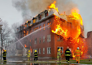
Figure 1. Fire Fighting in Buildings
2. The exits shall be so placed that they are always immediately accessible and each is capable of taking all the persons on that floor as alternative escape routes may be rendered unusable and/or unsafe due to fire. 

3. Escape routes shall be well-ventilated as persons using the escapes are likely to be overcome by smoke and/or fumes which may enter from the fire. 

4. Fireproof doors shall conform rigidly to the fire safety requirements. 

5. Where fire-resisting doors are employed as cutoffs or fire breaks, they shall be maintained in good working order so that they may be readily opened to allow quick escape of persons trapped in that section of the building, and also, when necessary, prompt rescue work can be expeditiously carried out. 

6. Electrical and/or mechanical lifts, while reliable under normal conditions may not always be relied on for escape purposes in the event of a fire, as the electrical supply to the building itself may cut off or otherwise interrupted, or those relying on mechanical drive may not have the driving powder available. 

7. Lift shafts and stairways invariably serve as flues or tunnels thus increasing the fire by increased drought and their design shall be such as to reduce or avoid this possibility and consequent spread of fire. 

8. False ceiling, either for sound effects or air conditioning or other similar purposes shall be so constructed as to prevent either total or early collapse in the event of fire so that persons underneath are not fatally trapped before they have the time to reach the exits; this shall apply to cinemas, and other public or private buildings where many people congregate. 

9. Floors are required to withstand the effects of fire for the full period stated for the particular grading. The design and construction of floors shall be of such a standard that shall obviate any replacement, partial or otherwise, because experience shows that certain types of construction stand up satisfactorily against collapse and suffer when may first be considered as negligible damage, but in practice later involves complete stripping down and either total or major replacement. This consideration shall also be applied to other elements of structure where necessary. 

10. Roofs for the various fire grades of the buildings shall be designed and constructed to withstand the effect of fire for the maximum period for the particular grading, and this requires concrete or equivalent construction. 

11. Where basements are necessary for a building and where such basements are used for storage, provision shall be made for the escape of any heat arising due to fire and for liberating smoke which may be caused. 

12. The following requirements shall be provided for smoke extraction: 

(a) Unobstructed smoke extracts having direct communication with the open air shall be provided in or adjoining the external walls and in positions easily accessible for firemen in an emergency. 

(b) The area of smoke extracts shall be distributed, as far as possible, around the perimeter to encourage flow of smoke and gases where it is impracticable to provide a few large extracts, for example, not less than 3 sq. m in area, a number of small extracts having the same gross area shall be provided. 

(c) Covers to the smoke extracts shall, where practicable, be provided in the stall board and/or pavement lights at pavement level, and be constructed of light cast iron frame or other construction which may be readily broken by fire-men in emergency. The covers shall be suitably marked.

Thursday, June 14, 2018

DAMP PROOFING OF BUILDINGS

DAMP PROOFING OF BUILDINGS
Figure 1. Damp Proofing
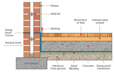
Damp Proofing: In order to prevent the entry of damp into a building, the courses, known as the damp-proofing courses, are provided at various levels of entry of damp into the building. The provision of damp-proofing courses prevents the entry of moisture from walls, floors and basement of a building.

Following methods are adopted to make a building damp proof:

1. Membrane Damp Proofing: This consists of introducing a water repellent membrane or damp proof course (D.P.C.) between the source of dampness and the part of building adjacent to it. Damp proof course may consist of flexible materials such as bitumen, mastic asphalt, bituminous felts, plastic and polythene sheets, metal sheets, cement concrete, etc. Damp proofing course may be provided either horizontally or vertically in floors, walls, etc. The provision of D.P.C. in basement is normally termed as tanking. 
The best location or position of D.P.C. in case of buildings without basement lies at the plinth level or in case of structures without plinth it should be laid at least 15 cm above the ground level. 

2. Integral Damp Proofing: The integral treatment consists of adding certain compounds to the concrete or mortar during the process of mixing, which when used in construction, act as barriers to moisture penetration. Such compounds are available in market in powdered as well as liquid form.
The quantity of water proofing compound to be added to cement depends upon the manufacturers recommendations. in general one kg of water proofing compound is added with one bag of cement to render the mortar or concrete water proof.
The compounds like alkaline, silicates, aluminium sulphate and calcium chlorides react chemically and fill in the pores to act water resistant.

3. Water Proof Surface Treatment: The surface treatment consists of application of layer of water repellent substances or compounds on these surfaces through which moisture enters. The use of water repellent metallic soaps such as calcium and aluminium oleates and stearates is much effective in protecting the building against the ravages of heavy rain. Bituminous solution, cement coating,transparent coatings, painting and distempering fall under this category. In addition to other surface treatments given to walls, the one commonly used is lime cement plaster. The walls plastered with cement, lime and sand mixed in proportions of 1:1:6 is found to serve the purpose of preventing dampness in wall due to rain effectively.

4. Cavity Wall Construction: This is an effective method of damp prevention, in which the main wall of a building is shielded by an outer skin wall, leaving a cavity between the two.
A cavity wall consists of two parallel walls or leaves or skins of masonry separated by a continuous air space or cavity. Cavity walls consists of three main parts, namely
a) the outer wall or leaf (10 cm thick) which is the exterior part of the wall.
b) the cavity or air space of 5 cm to 8 cm, and
c) the inner wall or leaf (min 10 cm in thickness) which is the interior part of the wall.
The two leaves, forming a cavity in between, may be of equal thickness or the thickness of the inner leaf may be increased to take the greater proportion of the imposed loads transmitted by floor and roof. The provision of continuous cavity in the wall efficiently prevents the transmission or percolation of dampness from outer wall or leaf to the inner wall or leaf.
Cavity type of construction is most desirable as it offers many advantages such as better living and comfort conditions, construction economy and preservation of dampness and also offers good insulation against sound.

5. Guniting: The process of depositing under pressure, an impervious layer of rich cement mortar over the exposed surfaces for water proofing or over pipes, cisterns, etc., for resisting the water pressure. Cement mortar consists of 1:3 cement sand mix, which is shot on the cleaned surface with the help of a cement gun, under pressure of 2 to 3 kg/sq cm. The nozzle of the machine is kept at a distance about 75 to 90 cm from the surface to be gunited. The mortar mix of desired consistency and thickness can be deposited to get an impervious layer. The layer should be properly cured atleast for 10 days.

6. Pressure Grouting: This consists of forcing cement grout, under pressure, into cracks, voids, fissures, etc. present in the structural components of the building, or in the ground. Thus the structural components and the foundations which are liable to moisture penetration are consolidated and are thus made water-penetration-resistant. This method is quite effective in checking the seepage of raised ground water through foundations and substructure of a building.

Sunday, June 10, 2018

BASEMENT EXCAVATION

The various methods of basement excavation are as follows:

Perimeter Trench Method: The perimeter trench method is used where weak soils are encountered; a trench wide enough to enable the retaining walls to be constructed is excavated around the perimeter of the site, and timbered according to the soil conditions. The permanent retaining walls are constructed within the trench excavation and the timbering is removed; the dumpling or middle can then be excavated and the base cast and joined to the retaining walls. This method could also be used in firm soils when the mechanical excavators required for bulk excavation are not available.

BASEMENT EXCAVATION
Figure 1. Perimeter Trench Method

Ground Anchorage Method: Ground anchor is basically a pre-stressing tendon embedded and anchored into soil or rock to provide resistance to structural movements by a “tying back" principle. 


Ground anchor can be classified into: 

1. Rock anchor – for anchorage in rock 

2. Injection anchor – suitable for most cohesive and non-cohesive soils 

BASEMENT EXCAVATION
Figure 2. Method to form Ground Anchor
Method to form a ground anchor: A hole is predrilled on soil or rock in position carefully calculated. For rock anchor, an anchor bar with expanded sleeves at the end is inserted into the hole. A dense high strength grout is injected over a required length to develop sufficient resistance to hold the bar when it is stressed. Stressing is by hydraulic mean and when the stress is developed, the head of the bar is hold by an end plate and nut.

For injection anchor, a hole should be bored usually with an expanded end to increase anchorage ability. The pre-stressing bar is placed into the bore hole and pressure grouted over the anchorage length. Gravel placement ground anchor can also be used in clay soils for lighter loading. In this method irregular gravel is injected into the borehole over the anchorage length to form an end plug. The gravel plug is then force into soil using percussion method through casing, forming an enlarged end. A stressing bar is inserted into the casing and pressure grouted over the anchorage length as the casing is removed.

Reinforced Concrete Bored Piles: There are two main types of RC bored pile retaining wall:

i. Contiguous bored pile retaining wall

ii. Secant bored pile retaining wall 

BASEMENT EXCAVATION
Figure 3. Contiguous Bored Pile Wall
Contiguous bored pile retaining wall: A contiguous bored pile is formed by constructing a series of individual vertical RC piles. The diameter of each pile in a contiguous piled wall is usually not less than 300 mm diameter. A small space usually of 100 mm is left in between adjacent piles. Once all the piles have been constructed the top of the piles are usually joined together by an RC capping beam. Contiguous piling is used in case of self-supporting soils such as stiff clays.


BASEMENT EXCAVATION
Figure 4. Contiguous Bored Piled Wall with RC Capping Beam
BASEMENT EXCAVATION
Figure 5. Basement Construction using Contiguous Bored Pile Wall
Secant bored pile retaining wall: Secant bored pile walls are made using two types of piles: a soft unreinforced pile and a hard, strong reinforced concrete pile. The minimum diameter of each pile in a secant pile wall is usually 450 mm. 
BASEMENT EXCAVATION
Figure 6. Secant Bored Pile Wall

The construction sequence is:

(a) A line of unreinforced piles is constructed using low strength concrete. These are the soft piles.

(b) Then a second line of piles is constructed between and overlapping with the soft piles. The second line of piles is reinforced and uses high strength structural grade concrete. These are the hard piles.

The hard piles provide the structural strength. The soft piles act to fill the gap between the hard piles and hold back any ground or water that would otherwise be able to flow between the hard piles. Secant piling is used where the ground has a perceived risk of becoming fluid, commonly due to the combination of non-cohesive deposits and water. This technique will reduce the ground water ingress if designed and constructed correctly.

BASEMENT EXCAVATION
Figure 7. Steel Sheet Pile Wall
Steel Sheet Piles: Sheet piled retaining walls are made by using interlocking steel piles. The steel sheet piles are generally driven or jacked into the ground using specialist plant. The plant is usually comparatively large which can be a limiting factor on their use. In addition head height clearance of at least the length of the sheet pile is required to allow installation. As a result steel sheet piles usually cannot be used underneath buildings. They are generally more suitable for open sites with good access as in the case of swimming pool.
Sheet piles are usually installed by either:
Percussive methods: hammering the sheet piles into the ground. This is generally not acceptable in urban areas due to excessive noise created by hammering.

Jacking: forcing the sheet piles into the ground using heavy hydraulic drivers.

QUICKSAND

The shear strength of a cohesionless soil depends upon the effective stress. The shear strength is given by:

Where = effective stress
φ = angle of shearing resistance
Let us consider a soil specimen of length L subjected to an upward pressure shown in figure 1. Let us consider the stresses developed at section C – C.
QUICKSAND
Figure 1. Quicksand Condition
When water flows in an upward direction through soil, the effective pressure is given by:


where ps = seepage pressure
If the seepage pressure becomes equal to the submerged weight of the soil, the effective pressure of the soil reduces to zero. In such a case, a cohesionless soil loses all its shearing strength and the soil cannot support any load. In other words, the soil particles ted to be lifted up along with the flowing water. The soil is said to have become ‘quick’ or ‘alive’ and boiling will occur. The popular name of this phenomenon is quicksand. It may be emphasized that quicksand is not a type of sand but only a hydraulic condition occurring within a cohesionless soil when its effective pressure is reduced to zero due to upward seepage force. Thus during the quicksand condition:


The hydraulic gradient ic at which the quick condition occurs is called the critical hydraulic gradient. For loose deposits of sand or silt, if void ratio e is taken as 0.67 and G as 2.67, the critical hydraulic gradient works out to be unity.
Seepage forces affect sands more than clays because sands do not possess cohesion, while fine sands and silts have some inherent cohesion which holds the soil grains together even at the critical hydraulic gradient. In sands, the shear strength s is given by:
Hence, when
In clays, however,
The cohesion component of shear strength is independent of . Boiling does not occur in coarse sands and gravels either, because these soils are highly pervious; hence, according to Darcy’s law, large discharges are required to produce a critical gradient of unity and such flows rarely materialize in practice.

QUICKSAND

When a natural soil deposit becomes quick, it cannot support the weight of a man or an animal. But contrary to common belief, the soil does not suck the victims beneath its surface. As a matter of fact, quick sand behaves like a liquid with a unit weight about twice that of water. A person can easily float in it with about one-third of his body out of quick sand. However, quick sand is highly viscous and movement in it would require a great effort and energy. A person may die by suffocation if he gets tired and let his head fall into the quick sand in panic.
If a person is caught in quick sand conditions, he should keep his head high above the soil surface and move slowly towards the bank. He should try to catch some tree on the bank and try to pull himself out of the quick sand.

FIBER REINFORCED CONCRETE

Fiber reinforced concrete may be defined as concrete made with hydraulic cement, containing fine or fine and coarse aggregate and discontinuous discrete fibers. The fibers can be made from natural material like asbestos, cellulose, sisal or are a manufactured product such as glass, carbon, steel and polymer. The purpose of reinforcing the cement based matrix with fibers are to increase the tensile strength by delaying the growth of cracks and to increase the toughness by transmitting stress across a cracked section so that much larger deformation is possible beyond the peak stress than without fiber reinforcement. Fiber reinforcement improves the impact strength and fatigue strength and also reduces shrinkage.

FIBER REINFORCED CONCRETE
Figure 1. Fiber Reinforced Concrete


FACTORS AFFECTING PROPERTIES OF FIBER REINFORCED CONCRETE

Fiber reinforced concrete is a composite material consisted of fibers in cement matrix either in an orderly manner or randomly distributed manner. Due to the presence of these fibers the properties of fiber reinforced concrete vary a lot. The factors affecting the properties of fiber reinforced concrete are given as under:
  1. Relative fiber matrix stiffness: For effective and efficient transfer of stress, the modulus of elasticity of the matrix must be lower than that of fiber used. The fibers of low modulus of elasticity such as polypropylene and nylon impart greater degree of toughness and resistance to impact as they have the capacity of absorption of large amount of energy, but they do not contribute to the improvement of strength and stiffness of concrete.
  2. Volume of fibers: The quantity of fibers used in fiber reinforced concrete is usually 1 to 5% by volume. The strength of the composite largely depends on the quantity of fibers used in it. With the increase in volume of fibers upto 1.5% tensile strength and toughness of the composite increases. The use of higher percentage of fiber is likely to cause segregation and harshness of concrete and mortar.
  3. Aspect ratio of the fiber: It is the ratio of the length to mean diameter of the fiber. The stress bearing capacity of the fiber depends upon its aspect ratio. The increase in aspect ratio upto 75 increases the ultimate strength and relative toughness linearly, but beyond this value of aspect ratio both the ultimate strength and relative toughness decreases.
  4. Orientation of fibers: It has been observed that the orientation of fibers influences a lot on the strength of concrete. The maximum benefit occurs when the fiber is unidirectional and parallel to the tensile stress. Experiments have shown that the fibers aligned parallel to the load offered more tensile strength and toughness than randomly or perpendicular distributed fibers.
  5. Workability and Compaction of Concrete: Incorporation of steel fiber decreases the workability considerably. This situation adversely affects the consolidation of fresh mix. Even prolonged external vibration failed to compact the concrete. Another effect of low workability is non-uniform distribution of fibers. The workability of the fiber reinforced concrete is improved by increasing the water/cement ratio or the use of some water reducing admixtures like plasticizers and super plasticizers.
USES OF FIBER REINFORCED CONCRETE

The following are the important uses of fiber reinforced concrete:
  1. Fiber reinforced concrete can be used for all types of works as road pavements, industrial flooring, bridge decks, canal lining, explosive resistant structures, refractory linings etc.
  2. Fiber reinforced concrete can also be used for the fabrication of precast products like pipes, boats, beams, stair case steps, wall panels, roof panels, manhole covers etc.
  3. Fiber reinforced concrete is also being tried for the manufacture of prefabricated formwork moulds of “U” shape for casting lintels and small beams.

WATER/CEMENT RATIO

The water/cement ratio is defined as the weight of the mixing water divided by the weight of the cement. High quality concrete is produced by lowering the water/cement ratio as much as possible without sacrificing the workability of fresh concrete. Actually water/cement ratio is an index of the strength of concrete. The strength of concrete mainly depends upon the strength of the cement paste and the cement paste strength depends upon the dilution of cement paste. In other words the strength of cement paste increases with cement content and decreases with water and air content.
For a fully compacted concrete, its strength is taken to be inversely proportional to the water/cement ratio. A typical curve of strength versus water/cement ratio is shown in Figure 1.

WATER/CEMENT RATIO
Figure 1 Compressive strength v/s water/cement ratio
ABRAM’S WATER/CEMENT RATIO LAW

Duff Abram carried out extensive experiments and on the basis of his experimental results he proposed a relation between the compressive strength of concrete and water/cement ratio in 1918, which is known as “water/cement ratio law”, which he presented in the following form:
Where, S = strength of concrete.
K1 and K2 = empirical constants
x = water/cement ratio

He suggested empirically the values for K1 as 14000 and K2 as 7 in F.P.S. system and K1 as 984 and K2 as 7 in M.K.S. units.
The values of K1 and K2 may depend upon the type of cement and aggregate, method of curing, age of concrete at which strength is desired and the mode of testing etc. 
Abram’s water/cement ratio law states that the strength of concrete is only dependent on water/cement ratio provided the mix is workable.
Abram’s law although established independently, is similar to a general rule formulated by Ferret in 1896. Ferret defined the strength of concrete in terms of volume fractions of cement, water and air. He expressed the compressive strength of concrete as:
Where S = strength of concrete
c, w and a = volume of cement, water and air respectively 
            K = a constant.
It may be recalled that the water/cement ratio determines the porosity of the hardened cement paste at any stage of hydration. Thus the water/cement ratio and the degree of compaction both affect the volume of voids in concrete, and this is why the volume of air in concrete is included in Ferret’s expression. 

GEL/SPACE RATIO

The influence of the water/cement ratio on strength does not truly constitute a law because the water/cement ratio rule given by Abram does not include many qualifications necessary for its validity. Some of the limitations of Abram’s water/cement ratio law are: 
  • The strength at any water/cement ratio depends upon the degree of hydration of cement and its chemical and physical properties. 
  • The temperature at which hydration takes place. 
  • The air-content in case of air-entraining concrete. 
  • Change of effective water/cement ratio. 
  • Formation of fissures and cracks due to bleeding and shrinkage. 
Instead of relating the strength to water/cement ratio, it is more appropriate to relate the strength to solid products of hydration of cement in the space available for formation of these products. Powers and Brownyard have established the relationship between the strength and gel/space ratio. This ratio is defined as the ratio of the volume of the hydrated cement paste to the sum of volume of the hydrated cement and of the capillary pores.


The compressive strength of concrete tested by Powers showed that the strength of concrete bears a specific relationship with the gel/space ratio. He found the relationship to be 240 x^3 where x is the gel/space ratio and 240 represents the strength of gel in MPa. The strength calculated by Powers’ experiment holds good for an ideal case. Figure 2 shows the relationship between strength and gel/space ratio. 
WATER/CEMENT RATIO
Figure 2 Relationship between compressive strength and gel/space ratio.
It is pointed out that the relationship between the strength and water/cement ratio will hold good primarily for 28 days strength for fully compacted concrete, whereas the relationship between the strength of concrete and gel/space ratio is independent of age.

CIVIL ENGINEERING OVERVIEW

Civil Engineering Overview
Civil Engineering is the oldest branch of Engineering, next to Military Engineering.
It is a professional branch of Engineering that deals with the analysis, design, construction and maintenance of the infrastructure facilities such as buildings, bridges, dams, embankments, roads, railways, pipelines, etc. Civil engineering is intimately associated with the private and public sectors, including the individual homeowners and international enterprises. It is one of the oldest engineering professions, and ancient engineering achievements due to civil engineering include the pyramids of Egypt and road systems developed by the Romans.


Engineering has been an aspect of life since the beginnings of human existence. The earliest practice of civil engineering may have originated between 4000 and 2000 B.C. in ancient Egypt, the Indus Valley Civilization, and Mesopotamia when humans started to abandon a nomadic existence, creating a need for the construction of shelter. During this time, transportation became increasingly important leading to the development of the wheel and sailing.
In the 18th century, the term civil engineering was coined to incorporate all things civilian as opposed to military engineering. The first self-proclaimed civil engineer was John Smeaton, who constructed the Eddystone Lighthouse. In 1771 Smeaton and some of his colleagues formed the Smeatonian Society of Civil Engineers, a group of leaders of the profession who met informally over dinner. Though there was evidence of some technical meetings, it was little more than a social society.


In 1818, the Institution of Civil Engineers was founded in London, and in 1820 the eminent engineer Thomas Telford became its first president. The institution received a Royal Charter in 1828, formally recognizing civil engineering as a profession. Civil engineering has a significant role in the life of every human being, though one may not truly sense its importance in our daily routine.
The function of civil engineering commences with the start of the day when we take a shower, since the water is delivered through a water supply system including a well designed network of pipes, water treatment plant and other numerous associated services. The network of roads on which we drive while proceeding to school or work, the huge structural bridges we come across and the tall buildings where we work, all have been designed and constructed by civil engineers. Even the benefits of electricity we use are available to us through the contribution of civil engineers who constructed the towers for the transmission lines.
In fact, no sphere of life may be identified that does not include the contribution of civil engineering. Thus, the importance of civil engineering may be determined according to its usefulness in our daily life.

Sub-disciplines Of Civil Engineering

Civil engineering is a multiple science including numerous sub-disciplines that are closely linked with each other. The main sub-disciplines of civil engineering are mentioned below: 
Structural Engineering: Structural Engineering is concerned with the structural analysis and design of foundations, buildings, towers, bridges, tunnels and other structures. The design and analysis should initially identify the loads that acting on a structure and the forces and stresses which arise within that structure due to those loads, and then designing the structure to successfully support and resist those loads. The loads can be self-weight of the structures, other dead loads, live loads, moving loads, wind loads, earthquake loads, loads due to temperature variation etc. Design considerations will include strength, stiffness, and stability of the structure when subjected to loads which may be static, such as furniture or self-weight, or dynamic, such as wind, seismic, crowd or vehicle loads, or transitory, such as temporary construction loads or impact. Other considerations include cost, constructability, safety, aesthetics and sustainability.

Geotechnical Engineering: Geotechnical engineering deals with soils, rocks, foundations of buildings and bridges, highways, sewers and underground water systems. Knowledge from the field of soil science, materials science, mechanics, and hydraulics is applied to safely and economically design foundations, retaining walls, and other structures. Environmental efforts to protect groundwater and safely maintain landfills have spawned a new area of research called geoenvironmental engineering. Identification of soil properties presents challenges to geotechnical engineers. Furthermore, soil exhibits nonlinear (stress-dependent) strength, stiffness, and dilatancy (volume change associated with application of shear stress), making studying soil mechanics all the more difficult.

Water Resources Engineering: This discipline of civil engineering concerns the management of quantity and quality of water in the underground and above ground water resources, such as rivers, lakes and streams. Geographical areas are analyzed to forecast the amount of water that will flow into and out of a water source. Fields of hydrology, geology, and environmental science are included in this discipline of civil engineering.

Transportation Engineering: Transportation engineering is concerned with moving people and goods efficiently, safely, and in a manner conducive to a vibrant community. This involves specifying, designing, constructing, and maintaining transportation infrastructure which includes streets, canals, highways, rail systems, airports, ports, and mass transit. It includes areas such as transportation design, transportation planning, traffic engineering, some aspects of urban engineering, queuing theory, pavement engineering, Intelligent Transportation System (ITS), and infrastructure management.

Environmental Engineering: Environmental engineering is the contemporary term for sanitary engineering, though sanitary engineering traditionally had not included much of the hazardous waste management and environmental remediation work covered by environmental engineering. Public health engineering and environmental health engineering are other terms being used. Environmental engineering deals with treatment of chemical, biological, or thermal wastes, purification of water and air, and remediation of contaminated sites after waste disposal or accidental contamination. Among the topics covered by environmental engineering are pollutant transport, water purification, waste water treatment, air pollution, solid waste treatment, and hazardous waste management. Environmental engineers administer pollution reduction, green engineering, and industrial ecology. Environmental engineers also compile information on environmental consequences of proposed actions.